3d Printing Help

Perhaps this should just be in the Maker thread, but I am seeking assistance with a 3d-print-based repair project

My family was recently gifted a very nice outdoor playset (swings, slide, rockwall, rope ladder, etc). This set was gifted by a family across the street that had 3 boys, so everything on it is “well used” to an extreme.

So far, the playset has been a hit with my four daughters (okay, okay… just the older three; the youngest is too young to play).

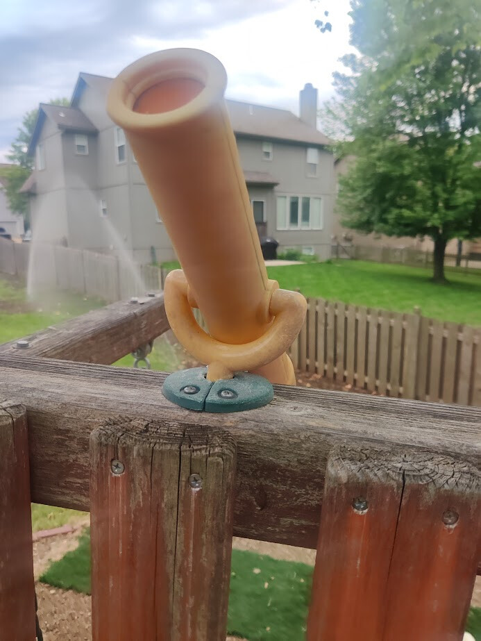
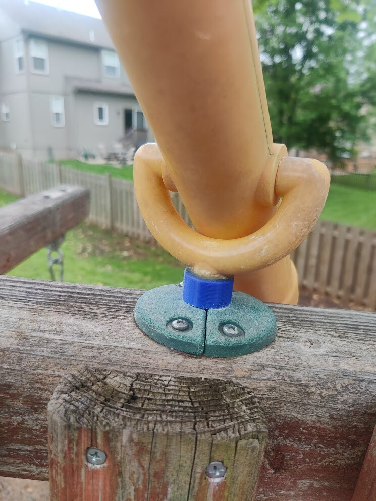
However, perhaps the bar can be raised. A week after the initial gift, the source family found some peripherals that had broken off over the years they had it. Apparently, the playset had originally been styled as a sailing ship; replete with helm’s wheel (broken off of original mounting point… easily relocated, no problem) and a mounted spyglass: here our real story begins.

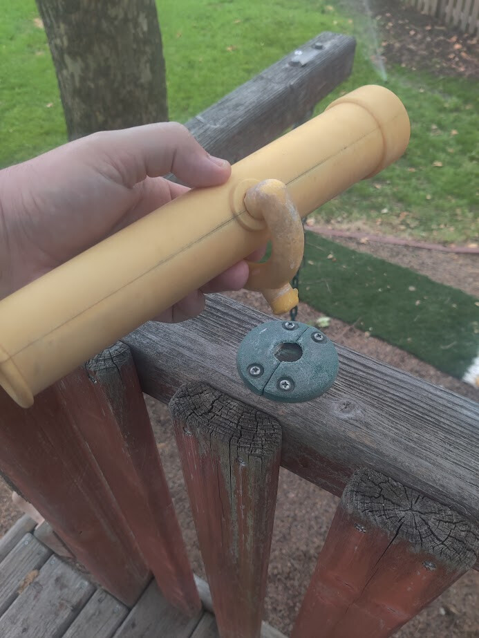
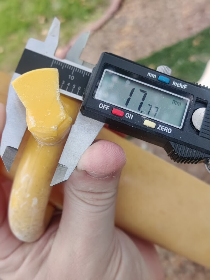
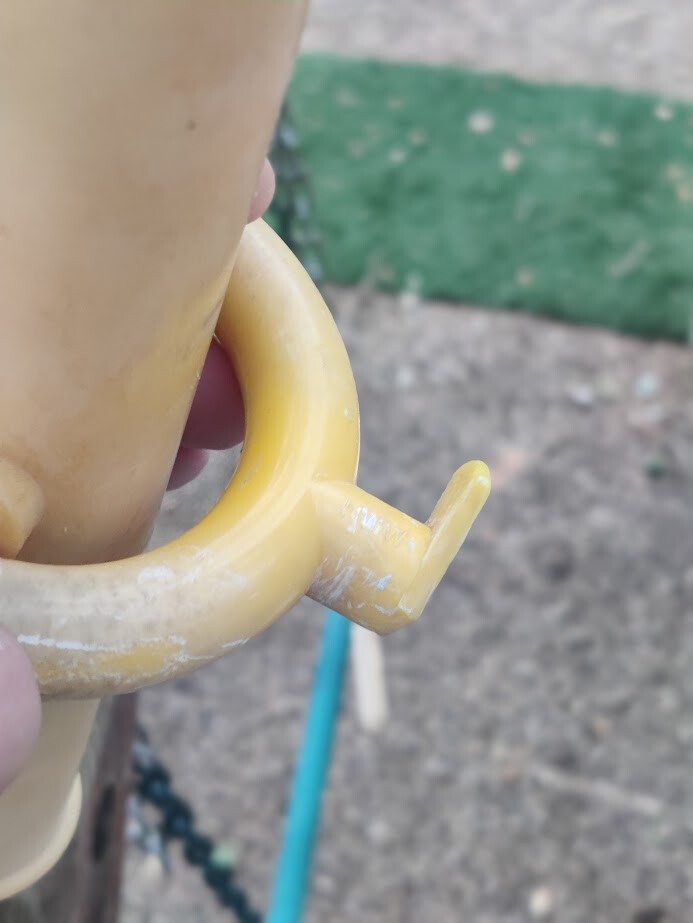
Here she mounts; or, at least, is supposed to. The flange that holds her affixed within the 2-part braket has broken; only a small vestige remains:

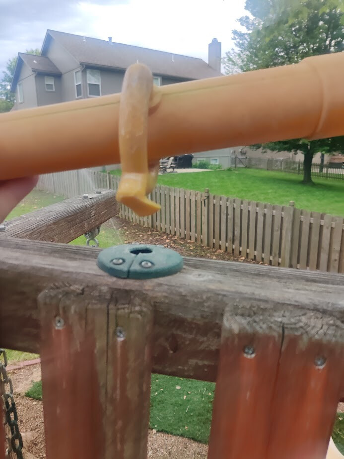
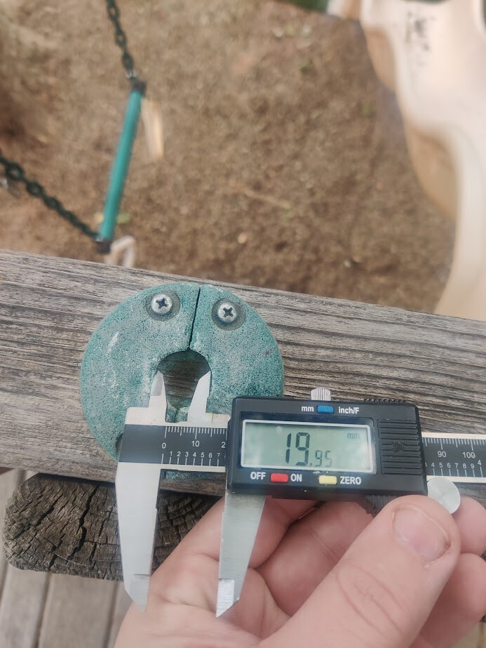
My digital caliper suggests that the original radius of the flange that is captured within this bracket is, roughly, 22mm. The shaft that connect between the flange to where the bracket splits has an outside radius of roughly 10mm.

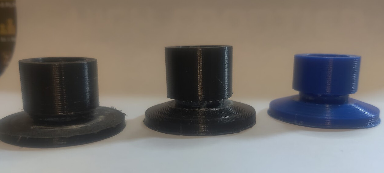
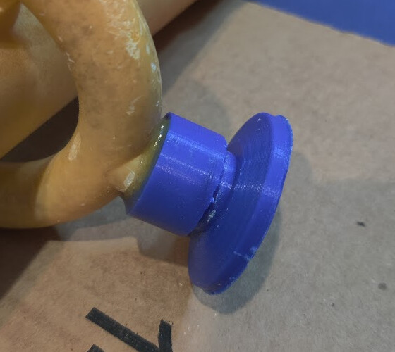
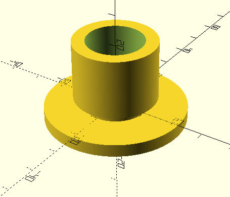
My current plan is to 3D print a piece with a flange that will seat within the original bracket. The spyglass piece has a good mounting bracket, but I plan to saw off the failed-and-broken flange part. And where this part sawed off, I plan to 2-part epoxy into this newly printed 3D printed piece.

Therefore, I need, roughly, a 3D printed part with a 22mm-radius flange at the bottom, a clearance of roughly 10mm-radius to fit within the aperture of the pre-existing bracket, and then a hollow socket within which I can 2-part-epoxy the doctored original spyglass mounting bracket.

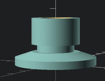
I cracked open OpenSCAD and came up with:

$fn=256;
union() {
    translate([0, 0, 3]) {
        difference() {
            linear_extrude(19) {
                circle(13);
            }
            linear_extrude(19.1) {
                circle(9);
            }
        }
    }
    translate([0, 0, -1])
        linear_extrude(5) {
            circle(10);
        }
    translate([0, 0, -4]) {
        linear_extrude(4) {
            circle(22);
        }
    }
}

Unfortunately, this builds with the dreaded Volumes: 2 output.

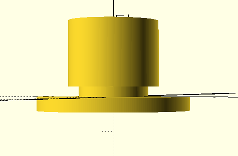
Maybe it’s just a matter of fudging my translate()s, but perhaps I’m missing something more fundamental?


1 Like

“Volumes: 2” is fine as long as you don’t get an error in STL export.

I would probably move the difference outside the union, though, and use cylinder. Usually I set the overlap as a variable epsilon because that reminds me later why it’s there.

$fn = 256;
epsilon = 0.001;

difference() {
  union() {
    cylinder(h = 4, r = 22);
    translate([0, 0, 4 - epsilon]) cylinder(h = 2 + 2 * epsilon, r = 10);
    translate([0, 0, 6]) cylinder(h = 19, r = 13);
  }
  translate([0, 0, 6 - epsilon]) cylinder(h = 19 + 2 * epsilon, r = 9);
}
1 Like

Wow this is totally the opposite of how I would do this. I typically drive it off Solidworks and generate an STL for the slicer. If it at all helps I’m happy to pull a CAD together for you if you want to sketch out the dimensions?

1 Like

This is crrtainly a personal taste thing: for complex tasks like this and page layout I’m muvh happier writing a program (OpenSCAD, Typst) than I am clicking and dragging stuff.

2 Likes

I’d look at this and be confident that a 3d printed part would break seconds after child-contact. My approach would be to get a massive thick washer with a small central hole. Drill out a central/axial hole up through the bottom of the existing piece and stuff some epoxy in it, then run a screw through the washer into it from below.

Much quicker than printing and much stronger than my experience of 3d prints of that thickness.

1 Like

This is a fair take on it. I was worried about the washer having that much play and giving the opportunity to throw a lot of weight into it and snap the existing mounting bracket

I’m guessing the PLA 3d print will hold up longer than the nearly 10-year old mounting bracket.

Time will tell. I’ll post an update on project progress in a day or so

2 Likes

Update: complete (?)

Using Roger’s rewrite as a base, I iterated a couple of times towards the final product.

$fn = 256;
epsilon = 0.001;

difference() {
  union() {
    translate([0, 0,11 - epsilon]) cylinder(h = 14              , r = 13);
    translate([0, 0, 7          ]) cylinder(h =  4              , r = 10);
    translate([0, 0, 4 - epsilon]) cylinder(h =  3 + 2 * epsilon, r1 = 22, r2 = 13);
    translate([0, 0, 0          ]) cylinder(h =  4              , r = 22);
  }
  translate([0, 0, 13           ]) cylinder(h = 19 + 2 * epsilon, r = 9);
}


Left: first iteration, with some tooling marks from trying to adjust fit with: file, saw, makeshift drill-press-based lathe
Middle: second iteration; added the sloped shoulder on the bottom disc, but the inset collar was not big enough
Right: final print, in blue by my eldest’s request

Printing was done with some basic supports in the collar/neck area; walls were set to 2mm (basically the entire thickness of some sections), and infill was otherwise set at 75%, to give the thing a snowball’s chance in hell to survive.


A very snug fit. A machinist would call this a slip fit, I believe. I mixed a very small amount (half a mL?) of 2-part epoxy in-place in the part, and then slowly seated the original piece down into it. I twisted the parts several times to help even out the epoxy that overflowed out the top


Finished product… for now

It has a very smooth action; I’m quite proud of myself.

We’ll see how PLA and my 10-year old epoxy holds up to the summer heat.

6 Likes